| Author | Message | ||
Paul White Experienced User Username: pjcwhite Post Number: 11 Registered: 2-2015 |
Hi Guys, continuing the popular theme of mystery items... As part of my braking system renovation, today I reinstalled my passenger side brake accumulator valve (RHD car). I still have to connect some pipes up to it, but at least it's in. I also replaced some of the existing low pressure brake hose with new EPDM and in the process broke a very brittle black hose about a foot or so in length which runs from what looks like a filter in the engine bay near the passenger side headlights to a "T" junction near the carbs. 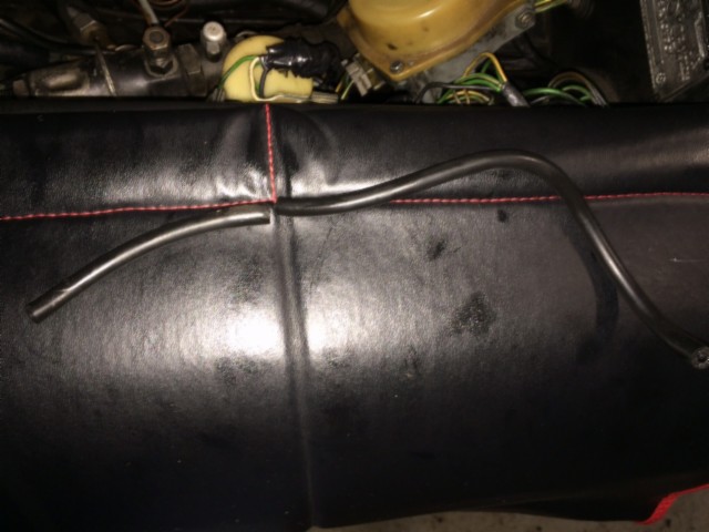 Knowing my luck, I'm guessing a fuel line. I'm not sure as it doesn't really smell of fuel (car not run for a month or so while I deal with the brakes). The hose was also only pushed onto stubs at either end and not secured (as I'd expect with a fuel hose). Starts here:- 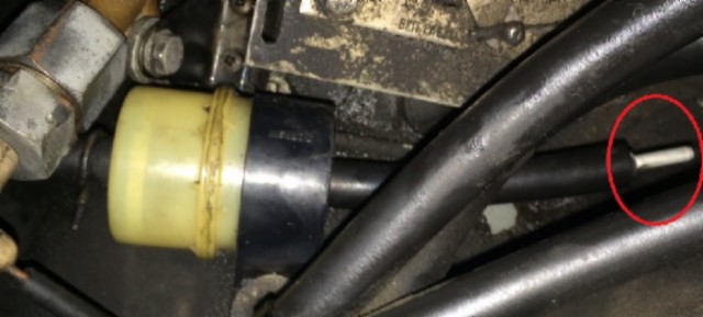 Ends here:- 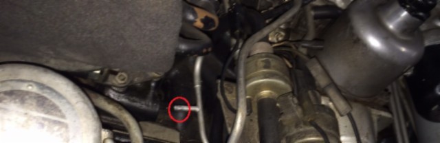 If it is indeed a fuel line I'll have to scour the engine bay for any more brittle hoses and replace them all (as I don't fancy driving around in a big Molotov cocktail). Thanks in advance Paul | ||
Paul White Experienced User Username: pjcwhite Post Number: 13 Registered: 2-2015 |
After perusing the manuals I think it's just a vacuum hose from the fuel thinner filter. | ||
Bob Reynolds Prolific User Username: bobreynolds Post Number: 286 Registered: 8-2012 |
It's part of the weakener system. The filter for the weakener system is near to the L/H headlight. It only contains air. | ||
Paul White Experienced User Username: pjcwhite Post Number: 14 Registered: 2-2015 |
Thanks Bob | ||
Brian Vogel Grand Master Username: guyslp Post Number: 1500 Registered: 6-2009 |
Paul, In The Shadow Owner's Companion, Jon Waples suggests one of the two best materials available for replacing the vacuum hoses in our cars is black silicone tubing. I've been using that and have to agree. It's long term durability and flexibility in a high-heat environment is far better than whatever the material was on the originals. It's always best to take a "one hose at a time" approach to doing vacuum replacement. Your car could have leaks that "have been adjusted for" that suddenly cause problems when a given leak is fixed or, conversely, you could introduce a leak unintentionally. It's far easier to locate the culprit for any issue when you replace, check running characteristics, replace, check running characteristics, than if you replace all at once. Brian | ||
Geoff Wootton Grand Master Username: dounraey Post Number: 828 Registered: 5-2012 |
Bob Quick question - Does your car have the evaporation loss control canister fitted. It is sited under the front left wing. Geoff | ||
Paul White Experienced User Username: pjcwhite Post Number: 15 Registered: 2-2015 |
Thanks Brian, I have a copy of that book too. I agree, black silicone is the way to go and one at a time approach sounds like a good plan. cheers Paul | ||
Robert Noel Reddington Prolific User Username: bob_uk Post Number: 281 Registered: 5-2015 |
Into Smug mode. My UK spec car doesn't have these parts. Less to go wrong. | ||
Bob Reynolds Prolific User Username: bobreynolds Post Number: 288 Registered: 8-2012 |
Neither does mine (anymore!)  | ||
Brian Vogel Grand Master Username: guyslp Post Number: 1508 Registered: 6-2009 |
Bob UK, Well, my UK spec car does. It doesn't have air injection and EGR, though. Brian | ||
Robert Noel Reddington Prolific User Username: bob_uk Post Number: 287 Registered: 5-2015 |
Brian, Well at least you don't have egr or air injection adding to the clutter. | ||
Geoff Wootton Grand Master Username: dounraey Post Number: 830 Registered: 5-2012 |
Bob, Bob_uk and Brian - I appreciate your responses as I am trying to figure out my weakener system. The fact that I now know the SY1s' did not have the canister fitted really helps. I hope you don't mind me pursuing this; Are your cars fitted with the weakener filter and if so, is there a cap on the unused short pipe that would normally take the vacuum tube that connects to the (missing) canister? The reason I am asking this is I am assuming the vacuum tube that connects the weakener device on the carb to the weakener filter should be sealed in some way. On my car, the tube just enters the weakener filter, which is just vented to the atmosphere. There is no vacuum. It appears that the weakener system could never have worked on my car, since the vacuum is being lost at the weakener filter. Or am I missing something here. Geoff | ||
richard george yeaman Grand Master Username: richyrich Post Number: 333 Registered: 4-2012 |
Geoff. my 1974 car has the weakener filter and also is vented to the atmosphere if I take the tube of at the carb and place my finger over the hole at the carb with the engine running the engine will stop. | ||
Bob Reynolds Prolific User Username: bobreynolds Post Number: 291 Registered: 8-2012 |
My car did have the filter fitted, on the left wing. Like yours it just vented to atmosphere. I don't understand why you thought this should be sealed in some way. If it was sealed you wouldn't get any air passing through the filter. | ||
Geoff Wootton Grand Master Username: dounraey Post Number: 838 Registered: 5-2012 |
I am trying to understand how the weakener system is implemented in these cars. The problem I had was, how is a (partial) vacuum created in the float bowl if part of the system is exposed to atmospheric pressure. Here is my first stab at it. The diagram below shows the system implemented on the SY1 cars. 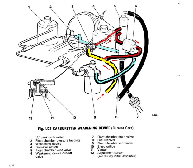 A venturi (not shown) strategically placed close to the throttle valve allows a varying negative pressure to develop in a drilling that connects this venturi to the weakener device (3). At closed and full throttle valve opening, only slight negative pressure is produced. At mid throttle opening, maximum negative pressure is produced. This negative pressure is exerted on the float chambers to regulate the fuel mixture at the jets. From the diagram, air is sucked in through the yellow tube, through the weakener device, the drilling and into the main induction chamber of the carburetor. As the air rushes through the weakener device, it passes over another venturi that is connected to the float chamber. This creates the negative pressure in the float chamber. This negative pressure is then transmitted to the float chamber on the other carb, through the blue tubing. The blue tubing is connected through the float chamber vent valve (5). This allows the tube to carry out it's other function of draining the float, should a float needle jam open and the carburetor flood. I know this is all straightforward stuff, but the working of the rest of the system (the red circuit in the diagram) was a bit of a mystery to me, until I looked at it more closely. The key is component 10 in the diagram, the bleed orifice. So, the purpose of the red circuit is simply to bleed air from the system to reduce the negative pressure in the weakener device. The weakening device cutoff valve (6) is open when the engine is running. When the engine is turned off, it closes, shutting off the bleed circuit which causes maximum negative pressure through the weakener device, which leans out the mixture at the jets so much the engine stops. The anti-dieseling system. Does anyone know why the red circuit is directed through the component 5, the float chamber vent valve? I would be grateful for any comments, confirmation or corrections, but hopefully no derision. Geoff | ||
Bob Reynolds Prolific User Username: bobreynolds Post Number: 294 Registered: 8-2012 |
I must admit I never saw the need for this complex and klunky system. No other car has it, nor anything like it. I would bet that the Crew engineers that dreamt it up didn't even know how it worked. As I see it, manifold vacuum from the Weakener device (3) passes along the yellow tube (which is not open to atmosphere as shown, but goes to the filter, which would provide some restriction). When the engine is cold and the cut-off valve is closed nothing else happens. When the heat sensor warms up and the valve opens, the vacuum goes through the fuel receiver and into the float chambers through the blue tubes, thereby pulling up the floats and weakening the mixture. This is undoubtedly an over-simplification. I have no idea what the other red bypass tube does; nor the reason for the complex arrangement of channels in the weakener device. The anti-dieseling valve is a separate valve and not shown on this diagram. It is not fitted on my UK car (well, none of this junk is now!). The valve (6) switches the system off when the engine is cold. I have no idea what is inside the fuel receiver, but I was told it was just a one-way valve. It must be more complicated than that if it's got 6 tubes going into it! If you knew what was inside the fuel receiver, it might help to explain the purpose of the other red tube. | ||
Geoff Wootton Grand Master Username: dounraey Post Number: 839 Registered: 5-2012 |
Back to the drawing board. The interesting thing you mention is the heat sensor (4 - bi-metal switch). I forgot to check that out. I think the only thing you gain from running the weakener system is slightly leaner fuel mixture at cruising speeds and an anti-dieseling device. I doubt the leaner fuel mixture shows up much in improved miles per gallon and I would guess most cars do not have this dieseling problem. So, in a sense it is superfluous in these cars (SY1s') I think the Engineers were just laying the groundwork for the much more involved emissions system on the SY2s'. I still want to understand this system fully, so I will press on. I am interested in why the engine on Richards car cuts out when he removes the tubing at the weakener and places his finger across the hole. This does not happen on my car. As you mentioned, it would help if we knew what was going on in the fuel receiver. Regards Geoff | ||
Robert Noel Reddington Prolific User Username: bob_uk Post Number: 299 Registered: 5-2015 |
The fuel level in the float bowl controls the mixture the position of the float is irrelevant. I am not sure how this lot works. I think the vacuum pulls the fuel level in the main jet down a bit. Back into smug mode. My car is not so inflicted with vacuum using junk. In my imagination of a working engine using vacuum for other things is not desirable because it dulls throttle response in carburettor equipped cars. I imagine a sudden full throttle I want all the air to suck on the jets. Over the years I have seen alsorts of stuff connected to engine vacuum. Cul de sacs like brake vacuum servos are fine. As is gearbox vacuum modules. The Triumph 2000 had a diaphragm in a valve that was connected between the Stombergs and the engine inlets and the engine breather. I had about 6 different explanations of exactly how it worked. Troubles some device which because no one knew made troubles worse. I removed one system and connected the breather to the air cleaner the engine was much smoother on small throttle openings and when floored the engine pickup was very clean. | ||
Geoff Wootton Grand Master Username: dounraey Post Number: 840 Registered: 5-2012 |
First of all, many thanks to Bob R for clarifying how the weakening system works. Here is attempt 2 to explain it. As Bob said, there is no anti-dieseling device on the pre 75 SY1 engines. Although I was aware the later SY2 cars had a separate anti-dieseling valve, I had thought the system implemented on the SY1 was configured to apply maximum negative pressure in the float chambers when the engine was switched off to starve the engine of fuel, thus acting as an anti-dieseling device. This was wrong. There is no such function. Here is the new, amended diagram. 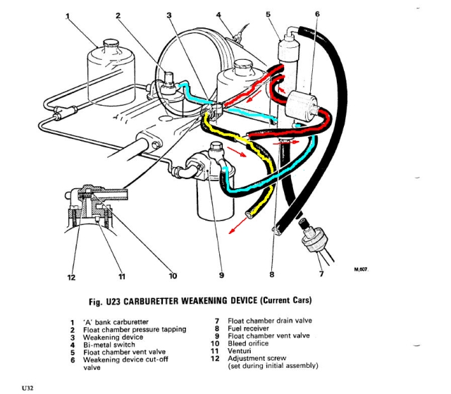 The venturi, located near the throttle butterfly valve on the left side carburetor, causes air to be sucked into the carburetor intake. This venturi is connected internally by a drilling in the carburetor body to the weakener device. This sucks air through the red circuit, in the diagram. This air rush passes over another venturi above the float chamber, causing negative air pressure above the petrol level. This negative pressure is communicated to the other float chamber, through the blue circuit. The yellow tubing is merely a vent tube to the weakener filter and canister (when fitted). When the weakening device cutoff switch (5) is turned off, no air can flow through the red circuit, so no negative pressure can be created in the float chambers. The weakening system is disabled. So, the only purpose of the weakening system is to lean out the fuel mixture when cruising, when the under bonnet temperature is above 16C. The manual cites this device as for emission control purposes, so I doubt this leaning out of the mixture adds much, if anything, to fuel economy. As for referring to this system as junk, I think Bob may well have a point - lol. The one nagging question - why does Richards engine cut out when he removes the tube at the weakener and places his finger across it? Any corrections to the above are welcomed. Geoff | ||
Bob Reynolds Prolific User Username: bobreynolds Post Number: 297 Registered: 8-2012 |
Geoff, I admire your tenacity in trying to figure out how this lot works. I don't think anybody has managed it yet. Here are 2 photos of the weakener device: 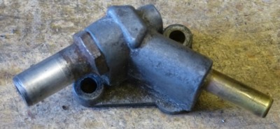 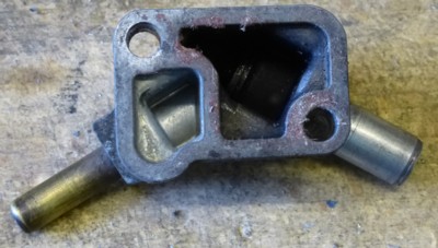 The two tubes are both connected to the large chamber underneath. There is an adjustable bleed in the large silver tube which restricts the airflow through that tube. The smaller chamber seen on the left does nothing. It's completely sealed. Just saving metal. The whole thing sits over a small jet-like protrusion near to the left-hand carburettor. This is Venturi (11). Studying the diagram, I cannot see any purpose for this. 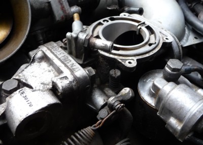 The tube with the bleed is the red tube going to the fuel receiver and the unrestricted tube is the yellow one that goes to the cut-off valve, and then into the fuel receiver. I haven't dismantled the fuel receiver so don't know what's in there. I think you can only take the top off. | ||
Geoff Wootton Grand Master Username: dounraey Post Number: 842 Registered: 5-2012 |
Hi Bob Thanks for the help and the new pics. I have made yet another mistake. As you said in a previous entry, the negative pressure is transferred to the blue tubes, in the fuel receiver. There is no venturi over the left carb float bowl. I was confusing it with a different type of carburetor. Here's a thing I am almost certain about. The small jet like protrusion that sits beneath the weakener housing connects via a drilling in the body of the carb to a small hole just above the throttle valve. This forms the venturi. In the picture below, taken looking into the "mouth" of the carb you can see the hole, pointed to by the black arrow. 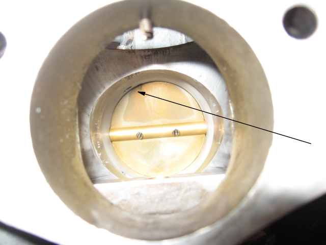 When the throttle valve is fully closed (as in the picture) the air flow across the hole is very slow. This is also the case on full throttle opening. When the throttle valve is partially open, air is squeezed past the hole, therefore increasing it's speed. This generates the variable vacuum which is proportionate to the throttle opening, maxing out at around half throttle. So, if you connected a manometer on this protrusion, you would see this variable partial vacuum as the engine revs were increased. The suction is transferred down the flexible pipe from the weakener device to the fuel receiver. There is a method in the fuel receiver (as you said) that transfers this vacuum along the flexible tubes to the float chambers. The higher the vacuum over the petrol in the float chambers, the leaner the mixture at the jets. I think all of the above is correct. The questions that remain: Why are their two tubes entering the weakener device Why is there a circuit around the fuel receiver (the red pipes in my photo. Why not locate the cutoff valve on the flexible tube that runs from the weakener device to the fuel receiver. My guess, in answer to the first question, is the vacuum is just too strong and needs to be regulated by more positive pressure from the wider tube. This is why there is an adjustable screw which restricts air input from the wider tube. This is obviously set in the factory. My guess, in answer to the second question, is if the cutoff valve was sited on the tube that runs from the weakener device to the fuel receiver, then on shutting it off, the float chambers would be completely sealed, quite possibly with a high vacuum in them. This would obviously cause all kinds of unpredictable behavior. My guess about the circuit around the fuel receiver is also to do with managing a controllable negative pressure in the float chambers. The only way to know precisely how the entire system works would be to cut open the fuel receiver and see how the internals are configured. Given the price of these things, I doubt that will ever happen. The good news is I am now sufficiently confident to know I need not be concerned about the weakener system on these cars. Any work I choose to do on it can be pushed right down to the end of the queue. Geoff | ||
Robert Noel Reddington Grand Master Username: bob_uk Post Number: 306 Registered: 5-2015 |
Is it legal to remove the system. | ||
David Gore Moderator Username: david_gore Post Number: 1690 Registered: 4-2003 |
Bob, It is illegal in Australia to remove any prescribed item from a vehicle unless it was fitted to a vehicle before the item became part of the vehicle's Australian Design Rules compliance specifications. For example, my partner's MY09 VW EOS diesel is fitted with a Diesel Particulate Filter to comply with European regulations but this was not required under the prevailing ADR specifications for Australian-delivered vehicles when the new vehicle was delivered to her. Accordingly, as I understand the current situation, there would be no penalties or refusal of registration if this filter is removed later in the life of the vehicle as it only has to comply with the requirements in force at the time the vehicle was delivered. | ||
Brian Vogel Grand Master Username: guyslp Post Number: 1527 Registered: 6-2009 |
Bob, Basically the same situation that Mr. Gore describes is true in the USA as well. That being said, enforcement depends on the ability of those doing inspections to know "what should be there" for a given year and model. Since most mechanics that do the safety and emissions inspections in localities here that require them wouldn't recognize what came OEM in a Rolls-Royce or Bentley engine bay there's a lot of latitude for those who wish to do removals to get away with it. Brian P.S. This also ignores entirely that most vehicles that are classified as antique are not required to have any emissions tests and, here in Virginia, do not have to undergo annual safety inspections. | ||
Geoff Wootton Grand Master Username: dounraey Post Number: 851 Registered: 5-2012 |
Hi Folks, As a point of interest (or not), I have not removed the weakener system. In fact it may even be working. It's difficult to tell without connecting up a manometer to the right side carburetor float chamber "valve". Since I have not got a manometer and since the system is so marginal anyway, I have decided I need not spend any more time on it. For the foreseeable future, anyway. Interestingly, I've never taken advantage of registering my car as a classic. I have always gone for a standard registration. In Nevada this required a smog test, which the car passed. Florida does not have a smog test or an annual safety test so I just registered it as standard. Geoff | ||
Bob Reynolds Prolific User Username: bobreynolds Post Number: 299 Registered: 8-2012 |
Well, I've been through 2 (UK) MOTs with the weakener system removed. As far as I know, the MOT is (mostly) concerned with safety issues. As the weakener system is not a safety item, you can do what you like with it. The car could have failed the emissions test without it, but it didn't. I re-tuned the carbs after the removal of the system, but I don't think it made any difference. The system doesn't do anything until the engine warms up, and it's probably not working properly on most cars anyway. You see a lot of cars with the flimsy wires broken off the otter switch on top of the air intake. My car was like that when I got it. It never failed an MOT. Apart from this, the inspector couldn't be expected to remember the underbonnet layout of the thousands of different cars that come through his door. So unless the removal of the weakener system showed up in another of the prescribed tests, he is never going to know that the system even existed. I know some countries have very strict rules about modifications to cars, where you can't even hang an air freshener on the dashboard without falling foul of some law, but fortunately the UK is not like that (yet). You've only got to visit a few Custom Car shows to see what you can get away with! Now insurance - that's a different matter! | ||
Robert Noel Reddington Grand Master Username: bob_uk Post Number: 310 Registered: 5-2015 |
My car is reg 1974. Because in 1974 the emission test was visible smoke only the tester just gives the engine a rev and looks for smoke. Actually checking the emissions with a machine is not applicable and of no legal standing. Even then its excess visible smoke. One of the reasons pre 1960s cars are mot exempt is because one cannot expect an old design to meet present regs. If the car couldn't pass a 2015 mot when new in 1959. One can hardly expect the car to pass 55 years later. In other words as the mot regs change to meet modern technology the regs aren't applied retrospectively. |