| Author | Message | ||
Jeff Martin Frequent User Username: jeff_r_1 Post Number: 476 Registered: 07-2018 |
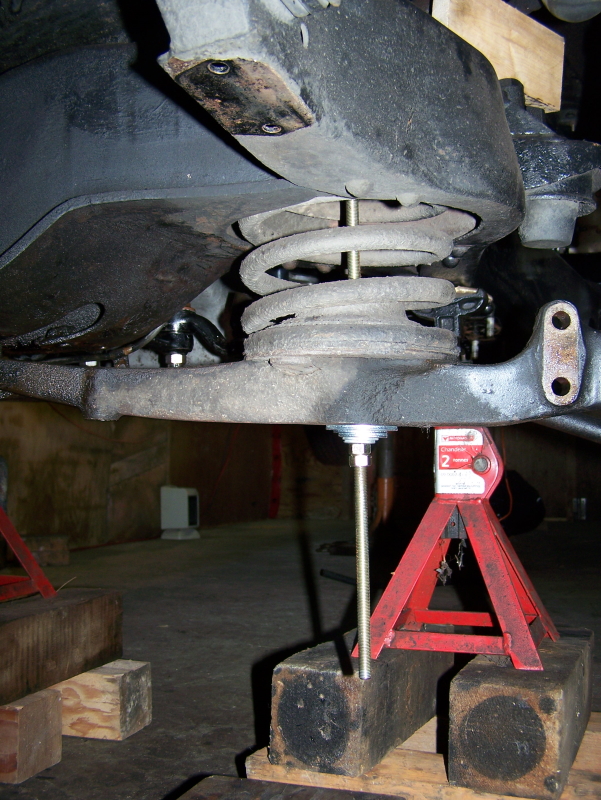 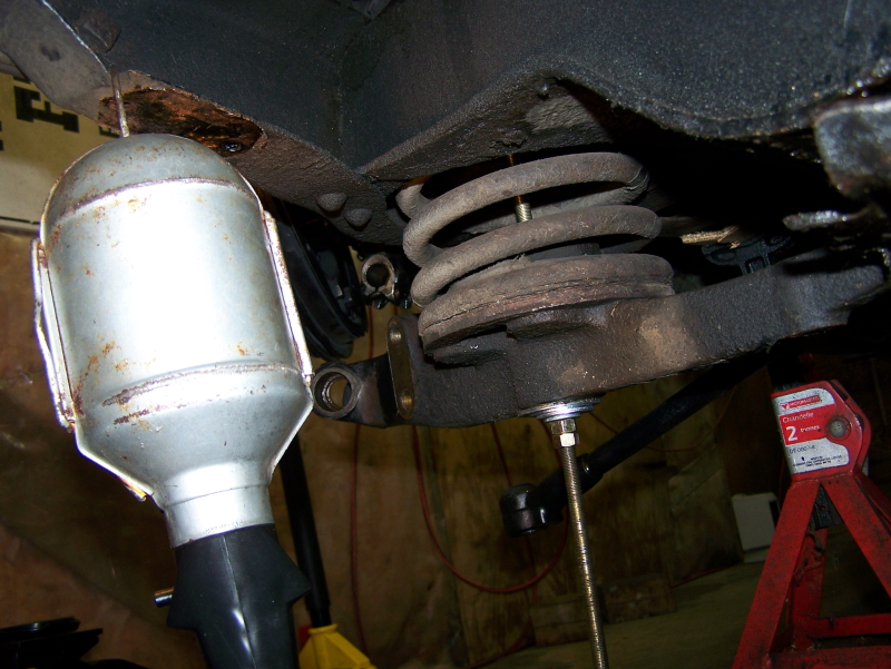 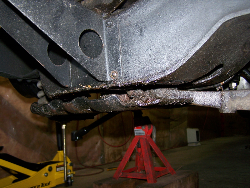 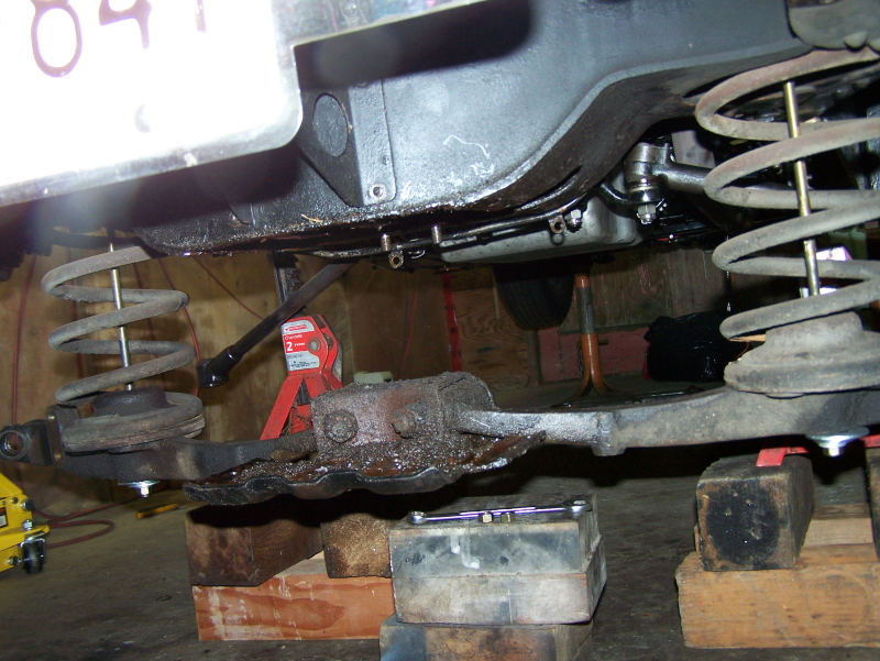 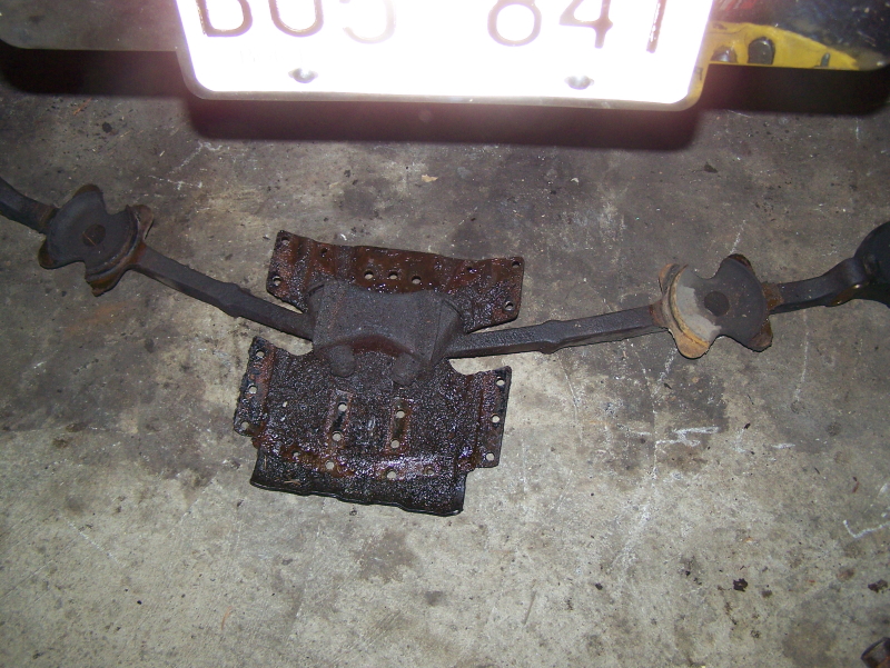 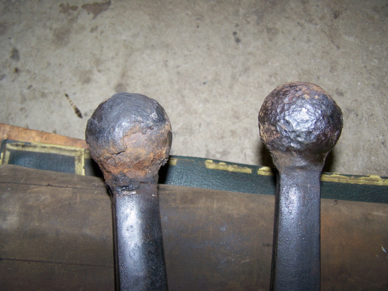 First two photos have high grade 3/8th ready rod compressing each spring; right and left sides shown. Loosening the nuts on the ready rod around 3 inches at a time on each side; skid plate beginning to lower. All tension off the springs and skid plate is hanging free _ I used the jack to support the skid plate when removing the nuts. Skid plate on the ground. Torque bar are ends totally rusted and unserviceable. If I had to do it again, I would slip the ready rod in with the car sitting statically while the tires were on. I had to move the jack stands out as far as I could on the control arms to lessen the arc to get the ready rod in. I had just enough length in the rod at 18 inches per side. I'll be making a jig to set the silent block bushings so they're correctly loaded on the control arms before installation. Normally I would tighten the bushings up with the car sitting statically on a level surface, but this can't be done in this case. Very odd why the bushings are mounted on the skid plate and not to the frame. . | ||
ChristopherCarnley Unregistered guest Posted From: 217.39.245.20 |
Not good practice. Introcar have 1 off new o/s RF6911, in stock. (Message approved by david_gore) | ||
Jeff Martin Frequent User Username: jeff_r_1 Post Number: 477 Registered: 07-2018 |
5/16 inch rod certainly would have been too thin, 1/2 inch would have been the best, but the 3/8 I used wasn't the junk from the hardware store. It came from a machine shop; they don't sell the junky stuff because of liability. I think if I use 1/2 to install it, I can compress the spring to move the lower front section control arm square enough to the frame to slip both them of them out. Regardless, the 3/8 rod showed no signs of failing, the nuts ran the entire length of the rods by hand after the fact, there was no reason for it to fail. I greased them off course with some moly as well. With out 2 of the factory spring compressors, one would really wrench the silent block bushing on that side, and then the other _ didn't want to do that; at least when installing each spring. I wasn't about to spend the 1200.00 US dollars on a one time use tool. I don't think there is anywhere to rent either. Yes, I am about to purchase that one from Introcar, I found a used one from Flying Spares, it is dirty, but it doesn't look rusted and it should polish up just fine. Thanks for your warning/advice. EDIT: I now I see there is also another tool that's needed to fully compress the spring for complete removal, that's another 500.00US dollars. 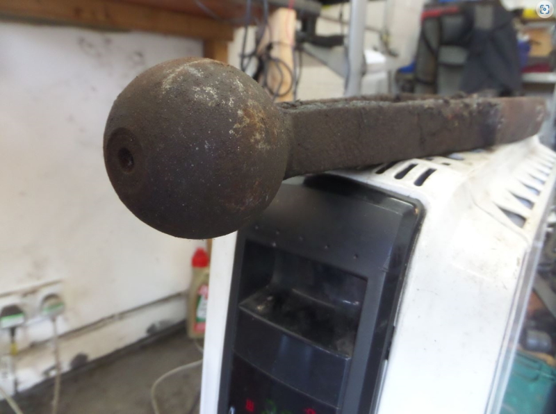 | ||
Jeff Martin Frequent User Username: jeff_r_1 Post Number: 498 Registered: 07-2018 |
Update photos: The lever shock shafts were OK except for the pitting where the original seals trapped moisture, so I had them surface welded with chrome and machined back to spec. This was expensive at 450.00$ Canadian per shaft, but still less expensive then the 480.00$ US it would cost to rebuild the entire unit _ I can do that myself. There are other rebuilders, but they're just too busy. One can clearly see the blue paint on the piston assembly still in place, the other lever shock used a lime green colour. Note the scribed line on the piston assembly near the castle nut for the correct orientation. The skid plate with new silent bushings pressed in and installed _ I still have to paint the bolts and castle nuts. The old bushing were not centred anymore and tired. Front of frame ready for paint; ideally the frame should have been removed and sand blasted, but I just don't have the room for that. It was a BEAR getting up inside the frame to clean and paint where the skid plate is bolted too _ VERY MESSY ! 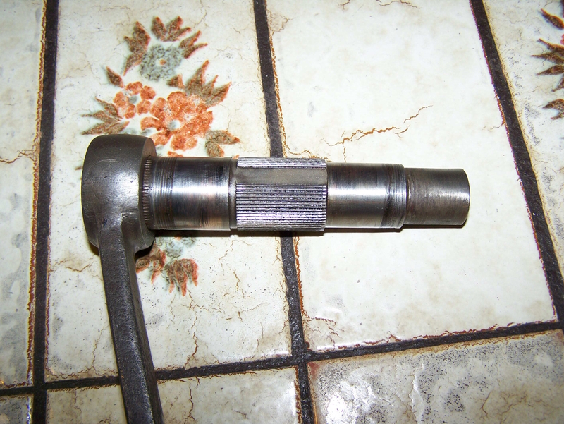 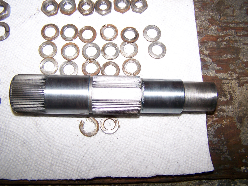 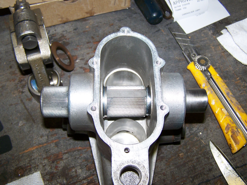 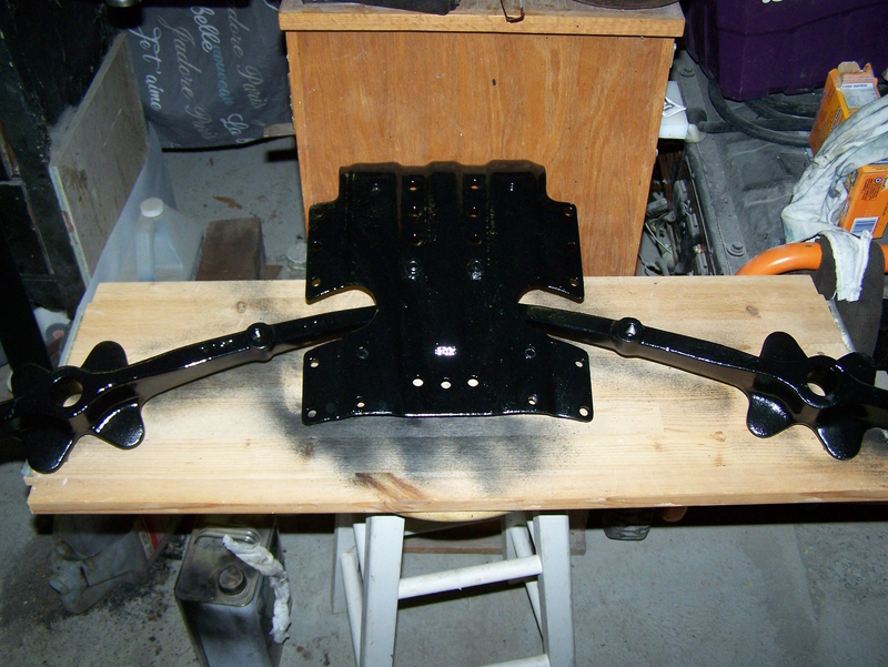 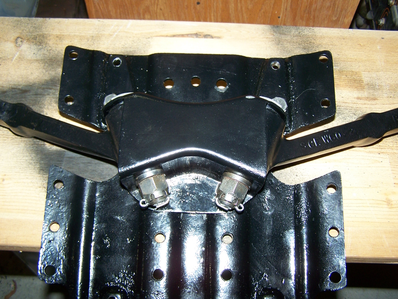 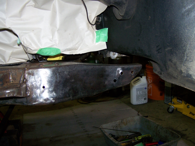 | ||
Jeff Martin Frequent User Username: jeff_r_1 Post Number: 501 Registered: 07-2018 |
The manual calls for S.A.E. 20 oil in the front dampers. Ronny at Ronny's garage just uses ATF which is SAE 10, that's a bit light. I was thinking a 0/20 SAE synthetic motor oil, it has anti foaming agents in it, so that may be a better choice; or there is just a straight SAE 20 that is meant for hydraulics made by Amsoil. Amsoil Compressor Oil Which one to use, or is it that important ? I would like to stay with synthetic. | ||
Bill Vatter Experienced User Username: bill_vatter Post Number: 154 Registered: 09-2004 |
You have the relationship of straight weight to multiviscosity oil backwards. SAE 0w-20 means it is like SAE 0 when cold, and like SAE 20 when hot. Therefore the oil that's equivalent to SAE 20 for this application would be SAE 20w-whatever. | ||
Jeff Martin Frequent User Username: jeff_r_1 Post Number: 502 Registered: 07-2018 |
Thanks for that, it would appear multi weight viscosity oil would not be appropriate, since the shocks are not an engine that will ever warm up. | ||
Philip Sproston New User Username: phil2025 Post Number: 44 Registered: 07-2006 |
jeff go to a bike shop and get some fork oil SAE20w it is anti foaming made for shocks.l use the same oil in SU. | ||
Jeff Martin Frequent User Username: jeff_r_1 Post Number: 503 Registered: 07-2018 |
Philip, if I can find some in synthetic fork oil, maybe; I was planning on going with ATF though, which is a little thinner then 20w. The front end of the car never was that smooth over the bumps, and I realize now that the oil in the shocks was too thick. Ronny (Ronny's Garage)recommends ATF, so I think I will go with that. Thanks very much for your post. | ||
Jeff Martin Frequent User Username: jeff_r_1 Post Number: 506 Registered: 07-2018 |
The new silent block bush on the upper end of the yoke sits "proud" on each end when installed, this made it very difficult to centre it. It did not press in easily, the press would build up pressure near the end and the bushing would suddenly move, and then too far. It could not be done carefully to get the centre. The original is flush with the yoke on each end when fully home, I don't know why the new ones could not be made in the same fashion, it would have made things much easier and less time consuming. The second photo doesn't quite show it, but the rubber is pretty much perished, the yoke was not rubbing hard up against the lever shock arm, but it was getting there. I made a brass spacer so the press would have a place to stop in order to achieve the bushings centre. The aluminum piece fits my press and the bushing so it would go in squarely. The brass spacer is turned down to about .090 thou. to get the bushing centred. I don't know what others did here, but this is what I came up with. 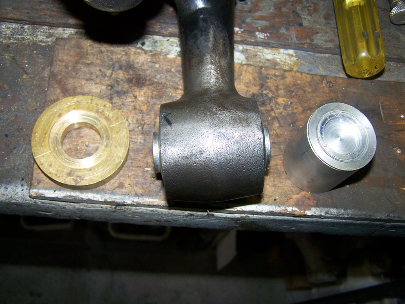 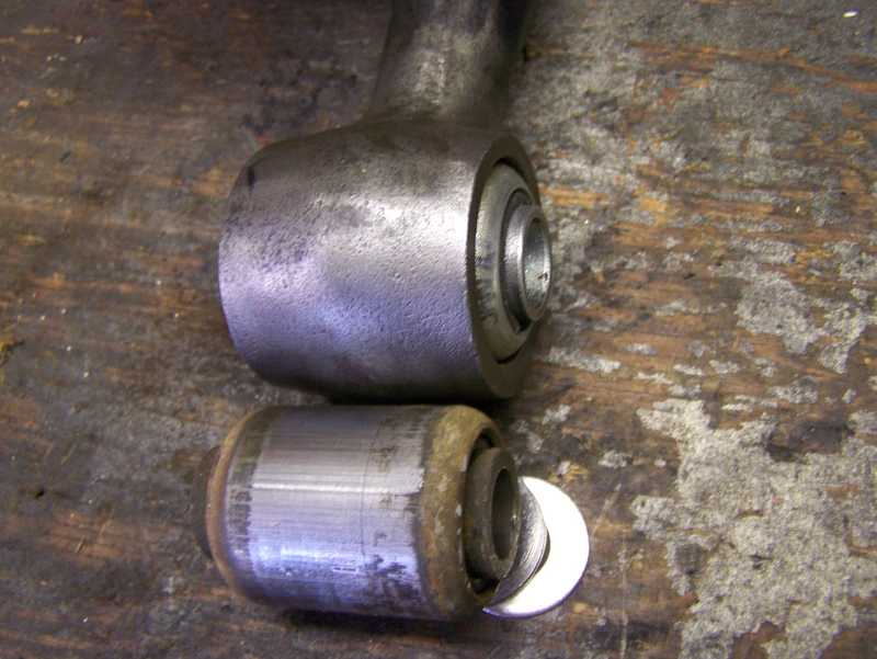 | ||
Bill Vatter Experienced User Username: bill_vatter Post Number: 155 Registered: 09-2004 |
I just press it in until the shell is even with the edges of the yoke. The upper bushing actually is not what positions the top of the yoke. The lower yoke bearings do that. When the lower bearings wear, the upper end is no longer securely positioned, and the forces on it will cause the top of the yoke to move forward. The rubber fails and the gaps between the yoke and the shock damper arms become unequal, with the gap at the front getting smaller and at the back larger. That is the best way to tell if there are problems at the bottom of the yoke; You check the gaps at the top. The rubber bushing is being stressed and owners will think, "I need new silentbloc rubber bushings at the top of the yokes." While that may be true, it is the bottom that has caused the upper to fail. Replace the silentbloc bushings, and that may correct things for a brief period, but soon the new rubber will fail again. When the above happens the steering geometry changes. The caster (castor in British spelling) angles become negative and the car no longer tracks well on the road. Camber angles become negative which affects tire wear and makes the car difficult to steer. The silentbloc bushings at the ends of the lower control arms located on the skid plate in the center of the car can also affect camber. However, those will generally last longer than the upper yoke bushings because they aren't highly stressed. If you want to set it up without any stress on the upper yoke bushings, put it together without the silentbloc bushing installed. Note the position of the upper end of the yoke between the shock damper arms. It should be center. Then you can see exactky where the silentbloc bushing should be positioned in the top of the yoke. If it isn't centered, something is wrong that needs to be corrected. Caster angle wedges at the bottom can be used to make alignment correction so that the car will track dead straight ahead. More positive caster angle on one side will make the car drift slightly toward the other side, or correct any tendency of it to drift to one side. If adding caster angle wedges causes the top of the yoke to move off center between the shock damper arms (moves toward the rear), then you shim between the lower control arm and the torque arm where those two bolt together. More positive caster angle on one side will make it drift towards the other side. | ||
Jeff Martin Frequent User Username: jeff_r_1 Post Number: 507 Registered: 07-2018 |
You said "I just press it in until the shell is even with the edges of the yoke". That's my point though, the shell on the new bushings go beyond the edges of the yoke, if you press the new bushing in until the shell is even on one side, it isn't on the other. It won't be centered at all, and I'm assuming it should be centered. The lower needled bearing were shot when I bought the car, the oiling system had failed due to lack of use and water was freely getting in there, it was a mess of black goo and bits of needle bearing crumbs. At the the time I got the car, more then 20 years ago, I'm not even sure if they were available, so I improvised and had a machine shop make up some solid bronze bushings with holes in the correct places so it would be oiled. 20,000 miles later, they are doing very well, just slightly polished where the weight of the car is on the bushings. I'll take some photos later. I'll check to see if the yoke is centred in the upper control arm in the mean time. The main problem is the torque arm balls and the rubber balls themselves, you can see them in my first post how bad things were, if anything that would certainly cause the geometry to be out. There was pretty much nothing left of the rubber balls. You said "If it isn't centered, something is wrong that needs to be corrected". Your statement refers to the lower needle bearings and its shaft _ I'll check the manual, but I don't know if they're even adjustable, fore or aft. The mechanic that did the alignment 20 years ago told me that the top bushing uncentres itself due to the torque placed upon it from acceleration, and even more so from a dead stop. The old tires were slightly worn on the inside of the tread indicating to me that it was towing out some, but it still tracked very well and was vey easy to steer. I'll will certainly check the tow in and tow out. | ||
NormanGeeson Unregistered guest Posted From: 81.99.74.184 |
Jeff That top bush was modified a few times by Silentbloc to “deter” the rubber moving forward under braking. Unfortunately, even though the bush is from their extremely heavy duty range the design could never prevent the rubber section moving forward under braking and eventually staying in the forward position. The best way is to fit the bush in a bias or off-centre position. You will then find that after a very short period the rubber in the bush will take on a “centre” position and the steering and suspension geometry will remain fairly accurate. I was taught that technique some 60 years ago, you need an offset of just under 0.125 inch from the normal bush position in the arm. (Message approved by david_gore) | ||
Jeff Martin Frequent User Username: jeff_r_1 Post Number: 508 Registered: 07-2018 |
Thanks very much for that. If I went to measure the bushing with its outer casing protruding from the upper yolk, it's probably 1/8 of an inch. I'm assuming it was made that way to achieve the off-centre position. I know the old bushings were tired as the upper yolk was almost coming in contact with the front facing lever shock arm. I could put the bushing in the vice and move the centre housing back and forth, and it would not return to its original position. | ||
Jeff Martin Frequent User Username: jeff_r_1 Post Number: 509 Registered: 07-2018 |
In the first photo, the red arrow shows just over a 1/16 of an inch, so pressing the bushing in all the way to the correct end should give the 1/8th of an inch, but I think I will just adjust my brass "STOP" to achieve the best results. Bill, the lower end bearings can be adjusted fore or aft by changing the shims arrowed in green, but there is no detectable wear on either end of the axle or the bearing cups. It's centred in the lower yolk now as it sits, we'll see how it goes together when the time comes. I plan on doing a mock assembly with out the springs; that will make things much easier. Third photo shows no wear on the bronze bushing after 21,000 miles _ it's polished and nothing more. If I remember correctly, the machinist put in no more then 2 to 3 thou clearance Fourth photo shows what happens to the axle arrowed in purple when the oiling system fails. The needle bearings start grinding into the axle creating the grooves you see under the weight of the front end. I never thought the needle bearings were such a good idea in the first place, given that there is not much movement there causing very limited rotation, It's just moving back and forth with the up and down motion of the front end, not like in a UV joint. 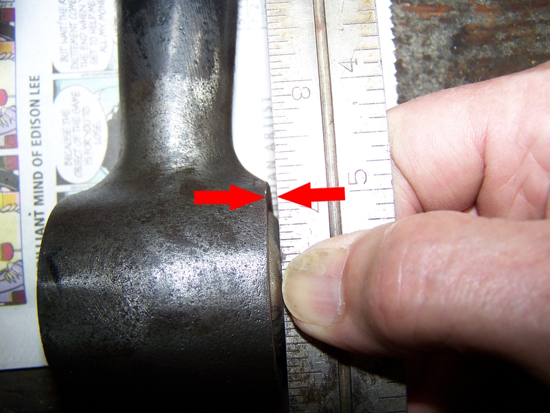 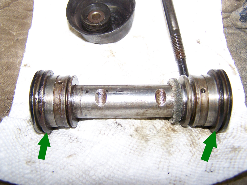  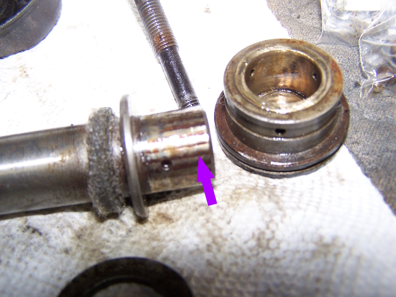 | ||
Jeff Martin Frequent User Username: jeff_r_1 Post Number: 510 Registered: 07-2018 |
Here's a photo of the top bush in the yolk where it has moved forward. (not my car) The worn rear torque arm rubber ball arm helped this problem along allowing the lower suspension to move forward. This also twisted the front block bushings as they are not centred anymore. The incorrect geometry also wore the inside of the tires, so it would seem, making it seem like the alignment was out. I'm not use if that would happen, but I'll know more when I assemble it back together and check the "tow in and tow out". 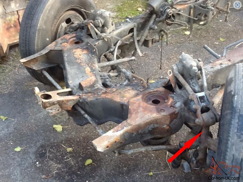 | ||
Bill Vatter Experienced User Username: bill_vatter Post Number: 156 Registered: 09-2004 |
Jeff, You apparently don't have the roller bearings in there. Not clear to me how the oil is getting to the rear bearing, which is now a bronze bushing. It is supposed to work with excess oil from the front bearing going into the center of the shaft through the oil hole. Then it exits the hollow shaft through the same hole on the back end to oil the rear bearing. I have found the factory parts work very well if the Bijur is used properly. On my cars I have replaced the felt seal at the front with an O ring that is under compression when assembled. This will force ALL of the oil to pass through the front rollers and go to the rear. At the rear I use the factory felt seal because the oil needs to flow freely to the back and escape through the felt. This is how water is purged from the bearing. My only point intended in previous posts is that the position of the yoke is controlled by the very close fit of the bearings at the bottom. The roller bearings, new rollers, new shaft, and new cups fit very closely, much closer than the 2-3 thousandths you say the bronze bushing has been fit. The 2-3 thousandths is too loose, but you probably need that for oil to get through the bushing. That looseness is one reason the silentbloc bushings at the top have failed. The assembly as modified with bronze bushings is requiring the silentbloc bushing at the top to hold the position of the upper end of the yoke. That puts axial stress on the rubber, which it is not designed to take, and the rubber fails. | ||
Bill Vatter Experienced User Username: bill_vatter Post Number: 157 Registered: 09-2004 |
So if you put it together on the bottom end, and then swing the yoke up between the shock damper arms, you will be able to see the alignment your parts have created. The silentbloc bushing, centered in the yoke should slip in between the damper arms, and it should not wiggle front to back because of looseness at the bottom. Adding caster angle wedges to correct any tendency the car has to drift to one side or the other will cause the upper end to move aft from more positive caster angle, or forward with more negative angle. That may require you to shim the joint between the lower triangle lever and the torque arm to get it to align properly. Or you could fit the silentbloc bushing off center in the upper end of the yoke to get it to align. | ||
Bill Vatter Experienced User Username: bill_vatter Post Number: 158 Registered: 09-2004 |
Incidentally, if I didn't already say this above, I applaud your method of lowering the center while simultaneously expanding the springs to keep the spring aligned straight without bulging out to any side. Doing it like you did prevents the springs frome flying out uncontrolled, which is the very serious danger associated with the front road springs. I cannot over emphasize the need to keep the springs straight while releasing the compression. Failure to do that is asking for a fatal injury. Anyone working on the front suspension needs to understand that and proceed very carefully. | ||
Jeff Martin Frequent User Username: jeff_r_1 Post Number: 511 Registered: 07-2018 |
I don't see how the clearance on the bushing effects the axial movement of the shaft (axle). It would effect the up & down movement of the yoke, not the sideways motion. I don't believe that the bushings I did are so sloppy that the top of the yoke will move so much that it would wear the block bushing. The end clearances were not changed when the bronze bushing were added, it was not worn and any sideways play (if any) from the axle shaft was deemed to be within spec. The 2 to 3 thou clearance gives 1 to 1.5 thou on each side of the bushing (top and bottom), like when one is turning down a job on a lathe. If you take 5 thou off, it's actually removing 10 thou, it works the same way here. 2 to 3 thou clearance over-all will give 1 to 1.5 thou on each side of the axle and bushing. I didn't want to go any less then that; there has to be some room for the oil to flow. I don't believe the amount of clearance of the bronze bushings will effect the top bushing so much that it would cause it to wear that much. As Chris said, "braking" is the problem, and in my case, the severely worn torque arms and rubber balls certainly did add to the problem allowing the whole thing to move forward. Also the block bushing have been in there probably since the car was new, the rubber is shot. About the flow of oil, the way I see the design, the hollow axle shaft acts like a reservoir, it fills up under pressure form the Bijur pump. The way I see it, keeping the reservoir full of oil is the important thing, not so much using the pressure for the Bijur pump to keep the bushings/needle bearing lubricated. I'll check into the O-ring as a seal, but looking at the wear pattern on the bushings after 21,000 miles, things look pretty good in there. When I do the mock-up I will post again, but that will be about 4 weeks as I stepped wrong off a ladder and fractured the 4th metatarsal bone in my foot. Not a bad fracture, but enough where I shouldn't be hobbling around on it. | ||
Jason Watson New User Username: crikeydawn Post Number: 6 Registered: 07-2023 |
Jeff forgive my ignorance, re first post what is the option if Torque bars are no longer available new and second hand is difficult? what is a ready rod? | ||
Jeff Martin Frequent User Username: jeff_r_1 Post Number: 516 Registered: 07-2018 |
I think there are lots of second hand torque arms available; there were a large number of cars made with that type of suspension _ it was totally changed in the S-Type and Cloud. I don't know why mine were so bad, but I found a used one at Flying Spares they had in stock, and shortly after they found another good used one, although by then I had already got the new one from IntroCar. Finding new-old stock is rare now, most parts are bought up pretty quick, keep in mind though, because I found a new one, that would indicate that they don't usually fail like mine did, otherwise someone would have snatched it up ages ago. Ready Rod (Canadian term maybe, and American): A pre-threaded rod from top to bottom that commonly comes in 3 foot lengths. You can see it in the first photo through the middle of the spring. What you see there is high grade steel obtained from a machine shop, not the junk from China you may find at the hardware store. If you strike it with a wretch, it has a nice ring/ping to it, where the Chinese one has this tin "clunk" sound to it _ probably made from reclaimed steel and other garbage. | ||
David Gore Moderator Username: david_gore Post Number: 4209 Registered: 04-2003 |
Jeff, Re your comment about "reclaimed" steel; if you have travelled on an Australian train, there is a very high probability that the train had wheels and axles made by Commonwealth Steel [Comsteel] in Newcastle NSW from recycled steel. This steel is melted down from scrap steel, analysed and the necessary alloying elements added before casting into ingots. These ingots are later cut into "cheeses" which are heated in a rotary furnace and forged to a round disc by a hydraulic press immediately prior to being hot rolled to its final shape on the historic rotary Edgewater Mill which is now or very close to being 100 years old. The wheel is then machined to its final shape and dimensions for making a new wheelset or repairing an existing wheelset; rare but can still occur if appropriate. Your comment about the "hammer test" is not strictly applicable as it has little relation to steel quality and is simply an indication of whether there is an internal defect in the item being tested and is almost always associated with the subsequent processing of the ingot after casting. A defective item will give a dull "thud" whereas a sound product will have a distinctive metallic ring sound. How do I know this? I was a metallurgist at Commonwealth Steel for 18 years including 10 years as a customer service specialist based in Sydney and Perth with the NSW Government Railways being one of my responsibilities. I had one of the best jobs in the Australian steel industry which gave me widespread experience in product application and problem solving. I now can look back and appreciate how fortunate I was to have been given this opportunity and experience.  | ||
Jeff Martin Frequent User Username: jeff_r_1 Post Number: 517 Registered: 07-2018 |
Here are two examples of crumby reclaimed steel, our old Ford delivery truck from about 1996. The frame on the truck was proper, where the paint had worn off, there was a thin film of surface rust, and when hit with a hammer it had a ring to it. The boxs' frame however had that clunky sound and huge flakes of rust were falling off from underneath the truck. The plywood inside was coming up because the anchors were coming lose due to loss of steel. There was a new bridge that was replaced in a majour city about a 2 hour drive from where I live. They initially got the steel at a good price from China. It was such poor quality apparently it could not be welded; I'm guessing that it had to many impurities in it. There were huge cost over-runs of course and many delays _ on down the line. In the end I guess you get what you pay for, I think the suppliers where the steel came from could have learned a lesson from Comsteel, or they just didn't care. While the ready-rod in the hardware store may not have any impurities in it, it's still not the same as the product from the machine shop. I don't know exactly what makes some steel better then others _ heat treated with more carbon, or less carbon ? The cheap bolts at the hardware store are too soft, that if you put any sort of real torque on them, they either strip, or twist off. Galvanized carriage bolts here in Canada are pretty cheap garbage, they're good for bolting together a kids tree house. I think it's more of a question on how well the steel is re-claimed, not so much defective. Here's a photo of the new bridge.  Open here.  | ||
Jeff Martin Frequent User Username: jeff_r_1 Post Number: 518 Registered: 07-2018 |
Here is one of the front bushings that mounts to the skid plate area, one can clearly see the centre is not in the centre anymore. Looks to be much tearing and shredding of the rubber itself. I attribute this to the rusty and ovalized torque arm balls and the failed rubber balls. I'm guessing at one time the torque arm ends were moving around in their housings, and eventually became tight again from rust and rotting rubber, and then settling in a wrong position that's way out of spec. I know there was steel on steel contact at the edge indicating that the torque arms had indeed moved forward. This caused the failure of the front control arm bushings and the top yolk silent block bushing to move forward in such an extreme fashion _ way beyond what braking could have done. My foot is getting better, and I've started to assemble things in my mock-up _ I'm confident that things will line up properly. Hopefully.... 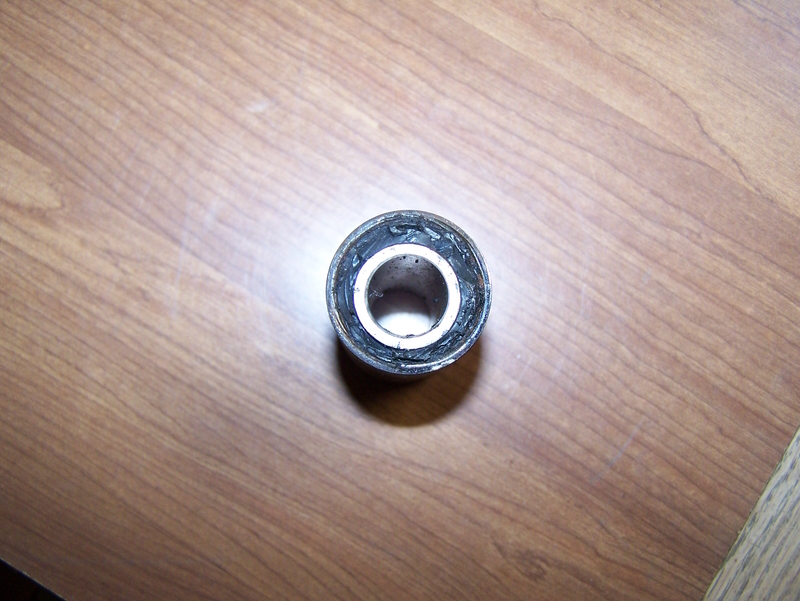 | ||
Jeff Martin Frequent User Username: jeff_r_1 Post Number: 520 Registered: 07-2018 |
Looking at that amount of off centre movement, that would be quite the amount out at the yolk. | ||
Jason Watson New User Username: crikeydawn Post Number: 12 Registered: 07-2023 |
David, donn't be too hard on the man. Find me some stailess steel made in China that doesn't rust. lol | ||
Jeff Martin Frequent User Username: jeff_r_1 Post Number: 522 Registered: 07-2018 |
How true that is.  | ||
Jeff Martin Frequent User Username: jeff_r_1 Post Number: 535 Registered: 07-2018 |
The failure of the front bushing (above post) was caused from severe sideways loading. When I assembled the right side, the torque and front control arm were so tight against each other, I had to use a screw driver to wedge things open to get the factory shim and bump stop plate in place _ I could not do it with my bare hands. The left side had a gap just the right width to allow for the shims. I increased the gap by tweaking the hole that the front control arm bolts into; it didn't take much, about 3/64. This ovalized the hole so I had the other side welded to add more material; the whole thing was filed down to a round hole again. The green arrow shows the gap I created, where the shims fill it in nicely like the left side. The blue arrow shows the forward movement of the control arm after moving the hole by 3/64. I know what everyone is going to say, but the torque arm was forcing it into the new position loading it's bushing sideways. By repositioning the front control arm, the sideways force on the bushing is gone. I would suspect that the loading of the bushing has been this way since the beginning. It would have taken many years to destroy the bushing. Note that the left side had the gap in it and allowed easy assembly. I am also going to say that the loading of the front bushing was also putting a great deal of "static" stress on the ball mount of the torque arm, decreasing its life. The upper end of the yolk is now centered in the lever shock, like on the left side and the factory shims are nicely held in place under a bit of pressure. 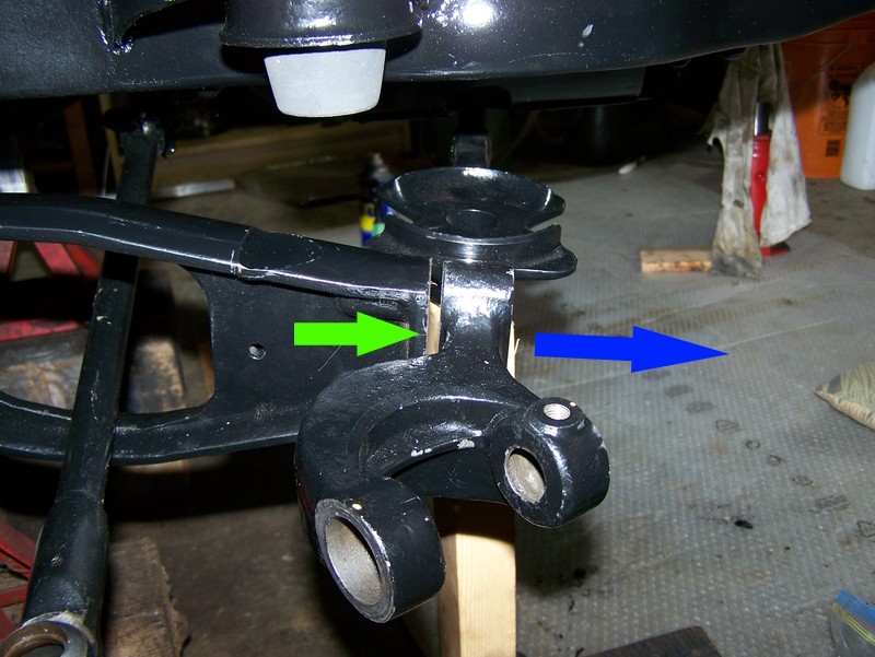 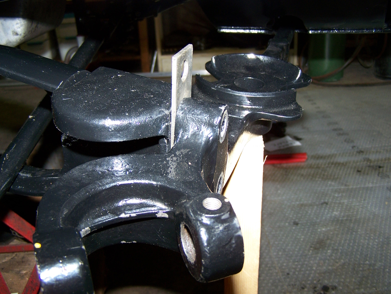 | ||
Jeff Martin Frequent User Username: jeff_r_1 Post Number: 536 Registered: 07-2018 |
OK, so I got lucky, I looked in the manual and the angle of the two 5/8 bolts are supposed to be at 22.5 degrees from centre, and after measuring it, it's with in the thickness of a pen/pencil line, it's the now the same as the left side that wasn't touched. I didn't have a piece of 5/8 stock, so the brass "round" I had just sat at the bottom of the circumference. I may do it again with the proper size, but I'm satisfied that it's close enough. The reprint of the manual I have at least was legible, the links here are so blurry and fuzzy, it can't be read at all. As far as I know the car was never in an accident, but who knows, usually an accident would have caused extensive visible damage, not just knocked the control arm off a number of degrees. I think it moved in the jig when it was being drilled or stamped. 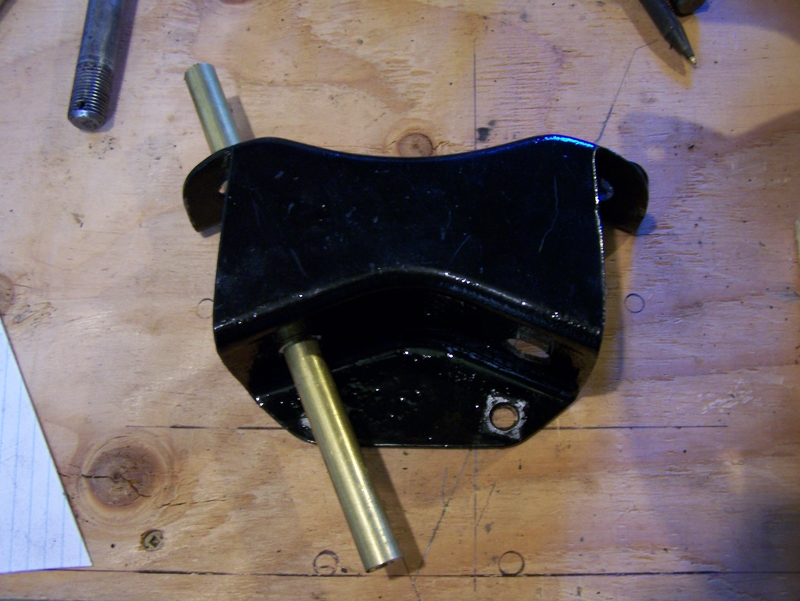 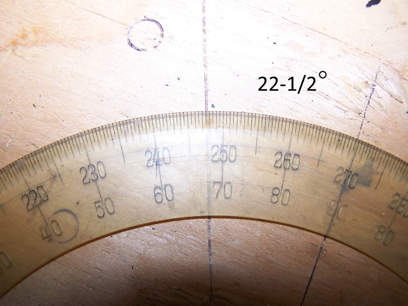 |